Transient waveforms
In TRAFOLO, transient simulations require a defined transient waveform. Users can generate basic waveforms parametrically, like square, sine, and triangular waveforms. However, since transformers and inductors are typically part of power converter topologies, their waveforms often differ from these basic shapes. To address this, TRAFOLO provides an option to import waveforms as a file.
For each transient waveform, TRAFOLO performs a Discrete Fourier Transform (DFT) to compute amplitude and phase. This guide will also explain how to convert a transient simulation into a harmonic analysis, transitioning from the time domain to the frequency domain.
To demonstrate the process of importing and analyzing transient waveforms, an existing Flyback transformer template in TRAFOLO is used as an example.
File Format and Importing
To accurately represent the waveform in a flyback transformer, data should be imported in a tabulated format such as CSV, XLS(X).
Make sure that the names in the first row describes the respective dataset, so that it is easier to identify and allot them in TRAFOLO.
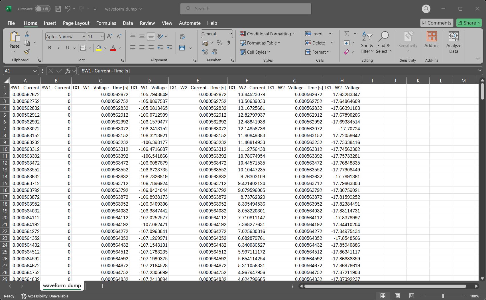
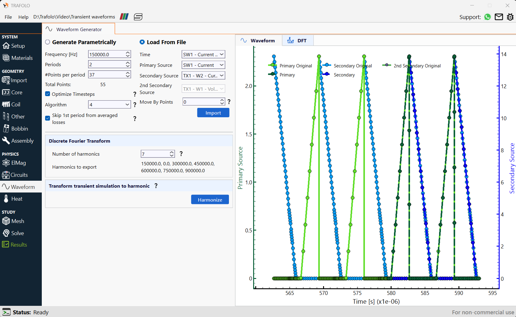
Click on Import under Load From File in the Waveform tab. Correct Time, Primary Source, and Secondary Source can be selected from the drop-down list, which contains the names of all the columns in the Spreadsheet file.
Interpolating Waveforms
Primary Original and Secondary Original refer to the imported waveforms. In some cases, the imported waveforms may contain fewer data points in regions with steep amplitude variations. Enabling the Optimize Timesteps option redistributes timesteps and interpolates waveform values accordingly. This improves simulation efficiency while maintaining accuracy in waveform representation.
Click on the A icon to scale the waveform to a visible range
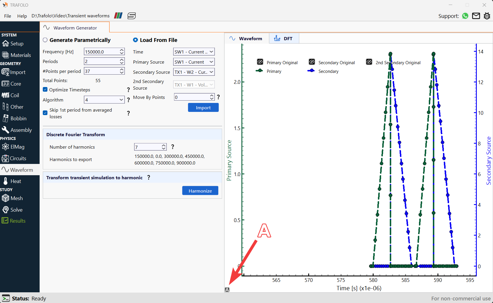
Algorithm 4 is chosen here. It identifies areas with the highest derivative and adds points there. It also considers steep changes in both primary and secondary waveforms for a balanced distribution. Choose Skip 1st period from averaged losses since the first period usually would have high errors due to mismatched phases between voltage, current, magnetic flux, and inrush currents, when compared with the rest of the periods.
Skip 1st Period from Averaged Losses – In transient simulations, the initial timesteps often exhibit high error due to phase mismatches between voltage, current, or magnetic flux, as well as inrush currents. When simulating more than one period, enabling this option excludes the first period from the time-averaged loss calculations to improve result accuracy.
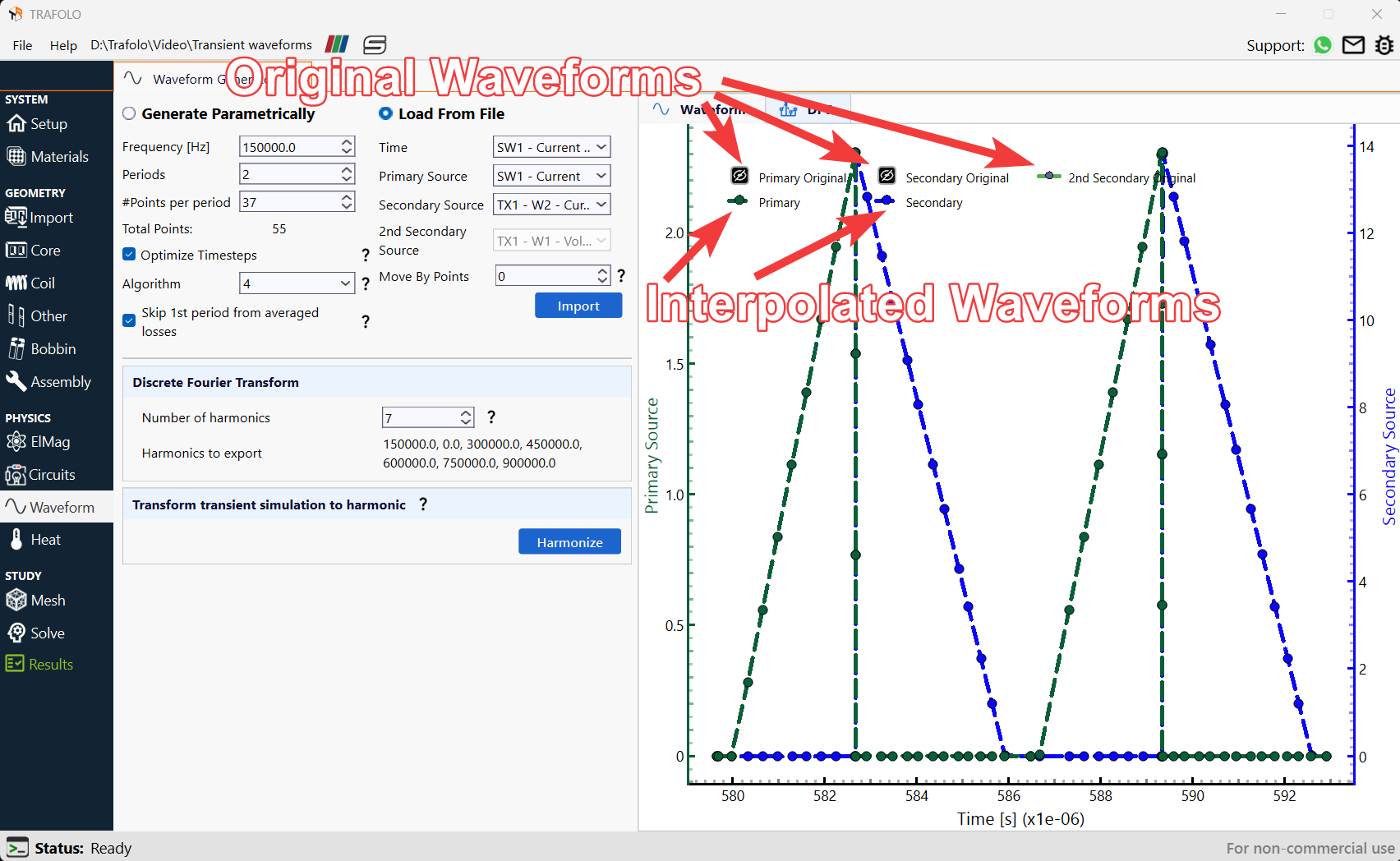
Optimizing Transient waveforms
Fundamental Frequency is set for period identification. Users must also specify the number of Periods and Points per period, however, Points per period is an approximate setting, the actual number of points used in the simulation may vary. For details on these settings, refer to Waveforms under to the Interface Reference Manual.
In TRAFOLO, the initial magnetic flux condition is set to zero. To minimize inrush currents or voltage spikes, users should ensure that the waveform starts at a phase where the magnetic field energy is minimal, if not done then there might be some DC bias for magnetic flux in the simulation. The Move By Points feature enables precise adjustment of the waveform's starting position, allowing better control over transient behavior.
Analyzing Transient Waveforms in Fourier Domain
When analyzing transient waveforms using the Discrete Fourier Transform (DFT), it is essential to ensure accurate representation of frequency components. Consider the following key aspects:
- DC Bias Verification: The 0 Hz component should be correctly accounted for. If a waveform has no inherent DC bias, it should not appear in the frequency histogram, except for minor numerical errors.
- Transformer Harmonic Analysis: In transformers, the voltage and current ratios at each frequency should align with the expected turn ratio. Any deviation may indicate leakage flux and weak coupling, affecting performance.
- Efficient Harmonic Selection: The software optimizes winding loss calculations based on a selected number of harmonics. The histogram helps identify significant harmonics, while those with negligible impact are disregarded. This reduces computation time and filters out harmonics caused by numerical noise. A smoother, sine-like waveform requires fewer harmonics for accurate representation.
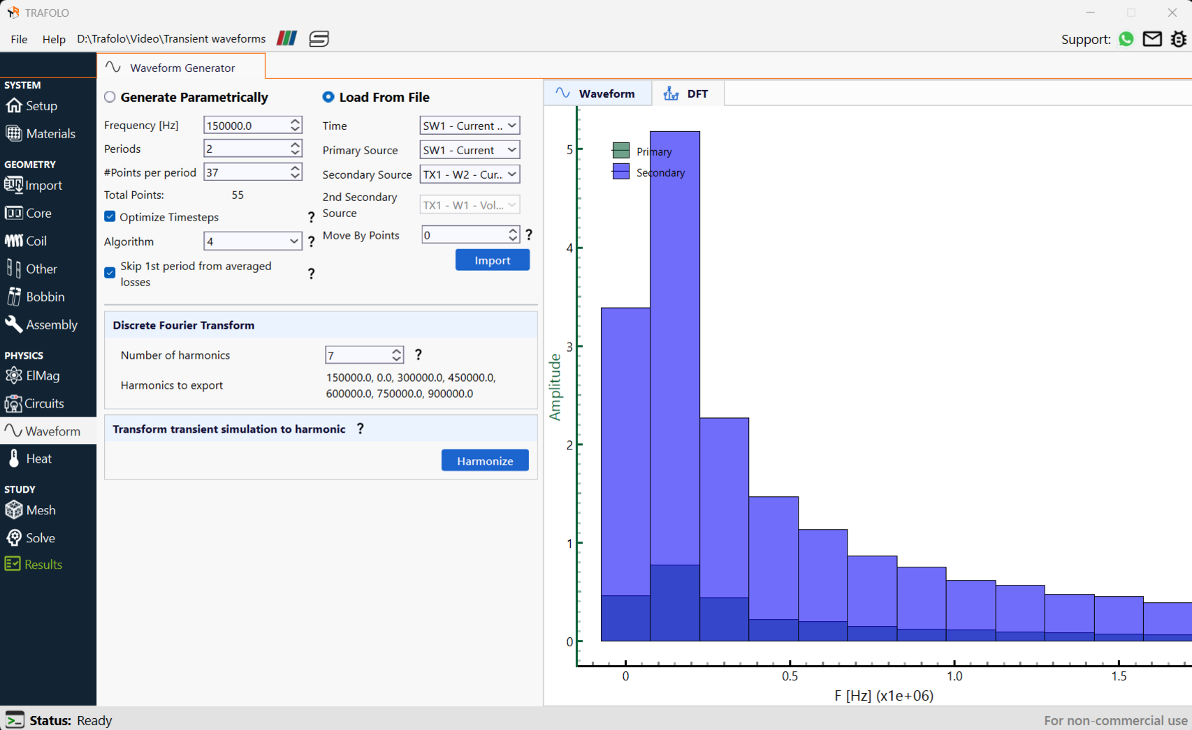
Harmonics are visualised under the DFT tab of the graph. TRAFOLO calculates the effective Rac/Rdc from DFT amplitudes and then applies the same to the entire waveform to then calculate the winding losses for transient simulation. This is applicable for Litz and Stranded wires, while for Solid wires, the current distribution from the windings will dictate the losses.
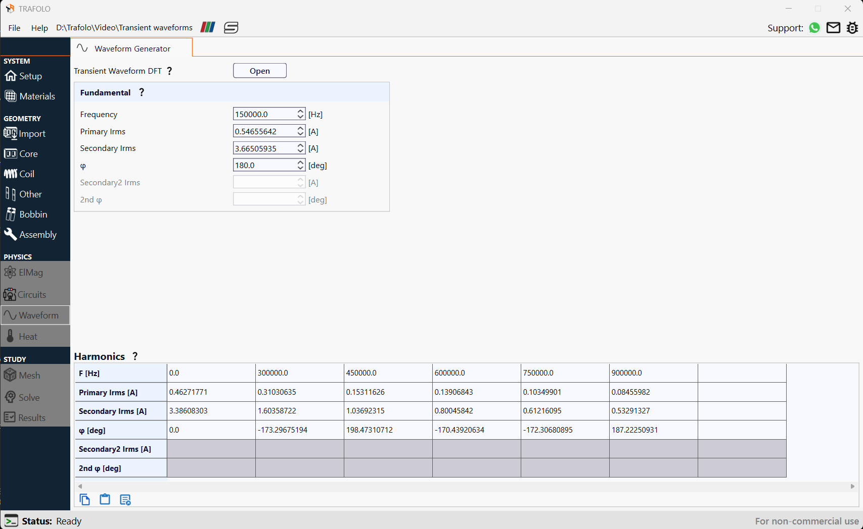
On clicking the Harmonize button, the simulation type changes to harmonic.